A case study demonstrating the performance and high-pressure capabilities of PA12 gas pipes, showcasing their ability to be an alternative to steel.
A case study for PA12 gas pipes in a high-pressure application (250 psi – 500 psi).
Introduction of PA12 Pipe
VESTAMID® NRG is a polyamide 12 (PA12) product specifically developed for energy efficient pipelines. For many years, steel was the only material available for gas distribution lines for pressures ranging between 120-250 psi and had no competition until the arrival of VESTAMID® NRG PA12. VESTAMID NRG PA12 withstands pressures far beyond 120 psi and is federally approved for operating pressures up to 250 psi. With high-pressure capability and installation practices similar to other plastic pipes, depicted in Figure 1 below, PA12 is an extremely practical solution for gas distribution lines.
As outlined in Figure 2 below, PA12 offers several advantages to extend the use of polymer gas pipes while addressing key challenges of steel gas pipes.
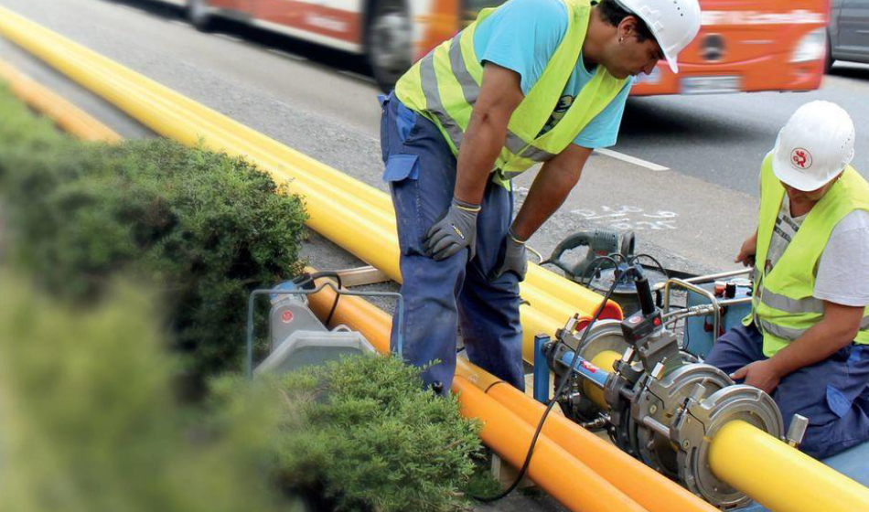
Figure 1. Fusion and installation of PA12 pipe for gas distribution. Able to be spooled in long lengths and joined on-site, PA12 simplifies pipe installation compared to steel.
HDPE
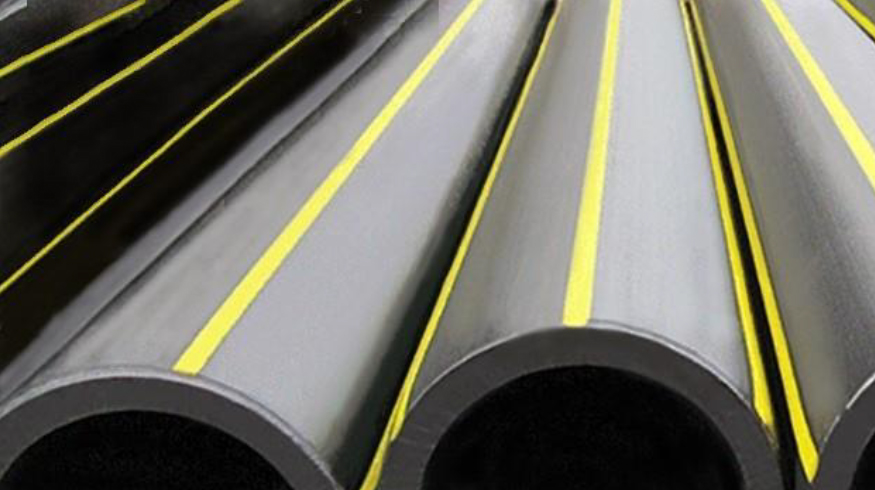
PA12:
- has higher operating pressures
- has higher operating temperatures
- has higher longevity
- does not de-rate in hydrocarbon contaminated soils
- has higher tensile strength (longer HDD lengths)
- employs the same installation methods
STEEL
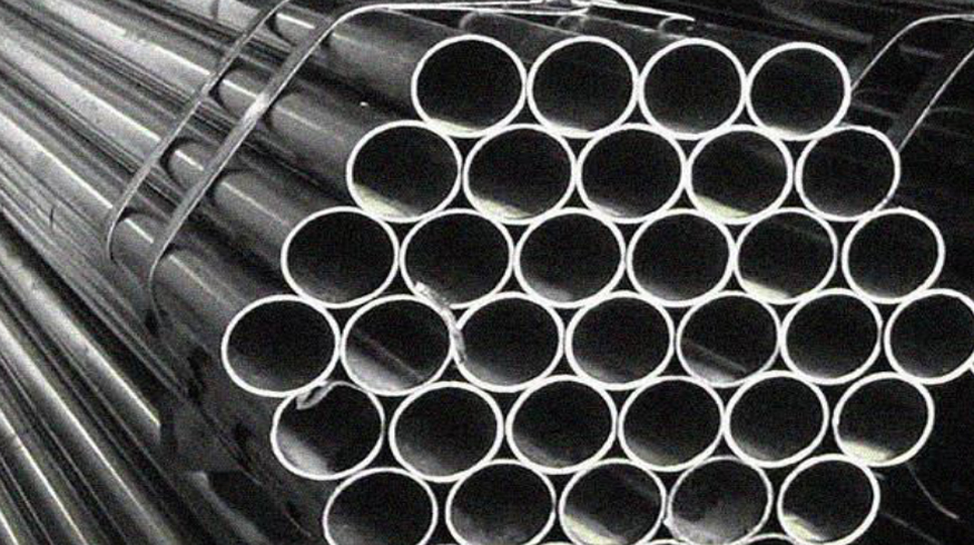
PA12:
- does not need cathodic protection (minimal lifetime maintenance cost)
- has smaller bend radius (longer HDD)
- is available in coils (faster installation)
- allows fusion joints (eliminates expensive welding)
more efficient logistics
Figure 2. Overview of the benefits of PA12 when compared with HDPE and steel.
As shown in Figure 3 below, PHMSA has issued a final rule that amends the Federal Pipeline Safety Regulations for plastic piping systems to include updated standards allowing and governing the use of pipelines made of PA12. With the inclusion of PA12 in the federal code, Evonik can now affect change in the industry by enabling utilities to replace low-pressure steel systems with a complete polymer system. So, whether it’s a solution to replace steel for increased pressures or a solution to upgrade pipelines affected by hydrocarbon permeation, Evonik’s PA12 is more than capable of safely and efficiently handling your pipeline needs.

Figure 3. PHMSA update to include PA12 pipe and components in the federal codes for gas distribution pipe
Pipe Fusion Testing
Background
During a fusion training process for field operations, CoServ observed small bubbles in the fusion area of pipe samples, as shown in Figure 4 below. Although small bubbles are acceptable per ASTM F3372 (Butt Fusion Joining of PA12 Pipe and Fittings), the team (CoServ, Evonik, and GROEBNER) wanted to better characterize the parameters needed to ensure good fusions. To do so, the team launched a project aimed at improving the fusion process to minimize bubbling in the fusion area and to maximize performance of gas distribution pipe installed by CoServ.
To achieve success, the performance of varying fusion parameters was evaluated through visual assessment of bubbling at the fusion surface, bend-back testing, tensile testing of control and welded pipe specimens, and sustained pressure testing of pipe sections. McSnapper testing at McElroy was also pursued initially but was determined to be unsuitable for testing of PA12 based on the guidance of McElroy.
All tests completed during the course of this project were aimed at ensuring the gas pipe system exceeded the performance requirements of ASTM F2785-21 (Standard Specification for PA12 Gas Pressure Pipe, Tubing, and Fittings). The team focused on achieving performance above and beyond the requirements for sustained pressure (hoop stress of 2,800 psi or higher) and burst pressure (hoop stress of 3,900 psi or higher).
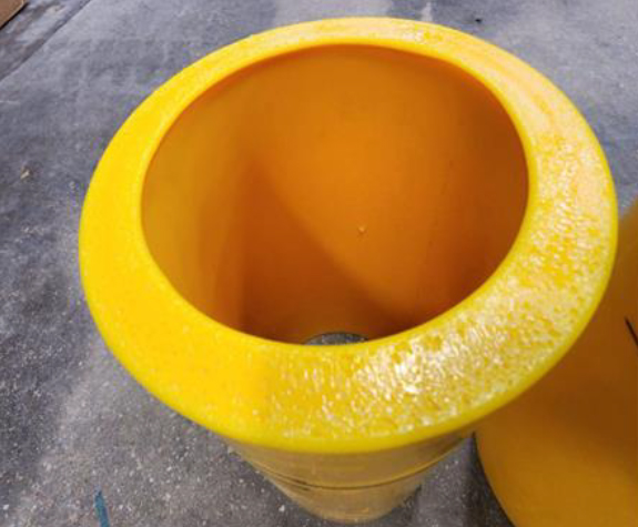
Figure 4. Example of small bubbles observed in the fusion zone of PA12 pipe. While such bubbles are not allowed for other types of plastic pipe, small bubbles can be common and acceptable in the fusion zone of PA12 pipe.
Standards
The test plan was set up in consideration of the relevant standards for PA12 gas distribution piping as outlined below, with a target of ensuring the gas pipe system exceeded the sustained pressure (2,800 psi) and burst pressure (3,900 psi) requirements of ASTM F2785-21.
- Minimum Hydrostatic Burst Pressure of Pipe Sections (Quick Burst): ASTM F2785-21 Section 5.6
- Sustained Pressure Testing of Pipe Sections: ASTM F2785-21 Section 5.7
- Fusion Quality Visual Assessment: ASTM F3372-20 Section 7.2.6.1
- In-Field Bend-Back Testing: ASTM F3372-20 Appendix X2.2
- Tensile Testing of Welds and Pipe Specimens: ASTM D638-22
Bend-Back Testing at Field Site
Field pipe installations continued while the weld parameter evaluation project was in progress. To ensure high-quality welds during this time, CoServ completed regular bend-back testing on-site in accordance with ASTM F3372-20 Appendix X2.2. Bend-back tests completed during this process yielded successful results (sample must be free of cracks and separations at the fusion joint location) indicating high-quality fusion was achieved in the field. Examples of successful bend-back test samples are shown in Figure 5.
Intertek Weld Strength Testing
Tensile testing of pipe specimens was completed by a third party (Intertek) to evaluate the strength of welds produced using varying parameters. The objective of this testing was to assess potential variability induced by varying weld parameters, gain an improved understanding of the performance of welds produced with varying parameters, and ensure optimal weld parameters.
Fusion parameters evaluated through the weld strength experiment were fusion temperature and fusion pressure. Two temperature ranges were used: nominal temperature (NT – 485-495 ˚F) and high temperature (HT - 500-510 ˚F). Three fusion pressures/ranges were used: nominal pressure (NP – 75-80 psi), high pressure 1 (HP1 – 90-96 psi), and high pressure 2 (HP2 – 110 psi). The tensile strength of welded specimens was then compared to the tensile strength of control (non-welded) specimens from the same section of pipe. Fusion parameters and resulting tensile strength values are listed in Table 1 below.
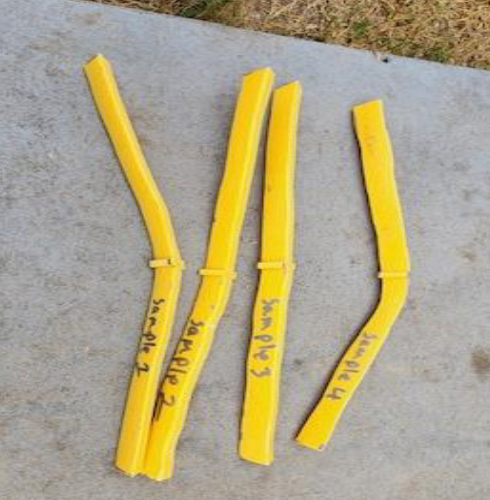
Figure 5. Examples of PA12 pipe specimens which exhibited high-quality fusion.

Table 1. Fusion parameters and resulting tensile strength values of welded and control (non-welded) specimens.
A couple of key observations were made based on weld yield strength results. First, high temperature fusion (505-510 ˚F) resulted in the highest weld strength (6,330 psi). Second, the varied weld parameters investigated resulted in a relatively small range of 250 psi weld yield strength (4.0% of the average weld yield strength). This demonstrates the consistent weld quality that can be achieved despite moderate variations in weld parameters. Last, while the high temperature fusion resulted in the best performance, all samples far exceeded the required yield strength of 3,900 psi (as specified in the Quick Burst test) as illustrated in Figure 6 below.

Figure 6. Results of tensile testing completed for welded and control (non-welded) pipe specimens. All results were compared with the baseline quick burst requirement of ASTM F2785.
Internal Sustained Pressure Test at CoServ
CoServ also conducted its own internal test to evaluate fusion performance. CoServ produced a section of PA12 pipe with multiple fusion zones using the same varied parameters (NT, HT, NP, HP1, and HP2) selected for weld strength testing at Intertek. CoServ then exposed the pipe and fusion zones to increasing sustained pressures for pre-determined time intervals. The first interval was a week at 1.5x MAOP (375 psi). CoServ then increased to 600psi and held for another week. During this time, small leaks were observed in the testing equipment that caused some delays. After repairing the leaks in the test equipment, CoServ increased the test pressure to 800+psi (more than 3x MAOP). Images of the test site are shown in Figure 7.
During ramp up, the pipe failed at 801 psi due to a ductile failure in the transition fitting. After assessing pictures of the fitting, consultation with the fitting manufacturer, and reviewing the data sheet, it was concluded that failure occurred at a transition in thickness in the fitting as shown in Figure 8 below. This was concluded to be the most likely failure location due to a stress concentration resulting from the thickness transition in the fitting (where the two pipe walls meet and the pipe wall thickness reduces). The promising test result of 801 psi suggests that PA12 pipes have potential to be operated at pressures much higher than 250 psi when applying a 1.5 safety factor.
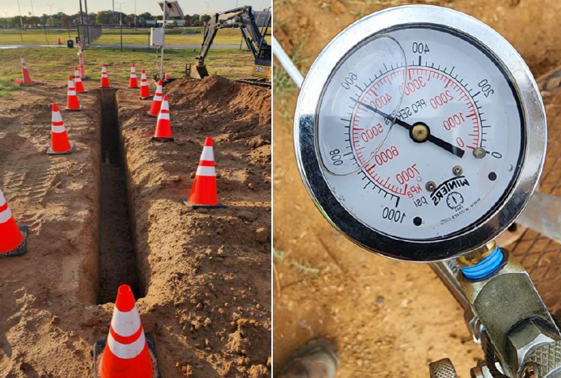
Figure 7. Test setup for sustained pressure testing completed by CoServ.
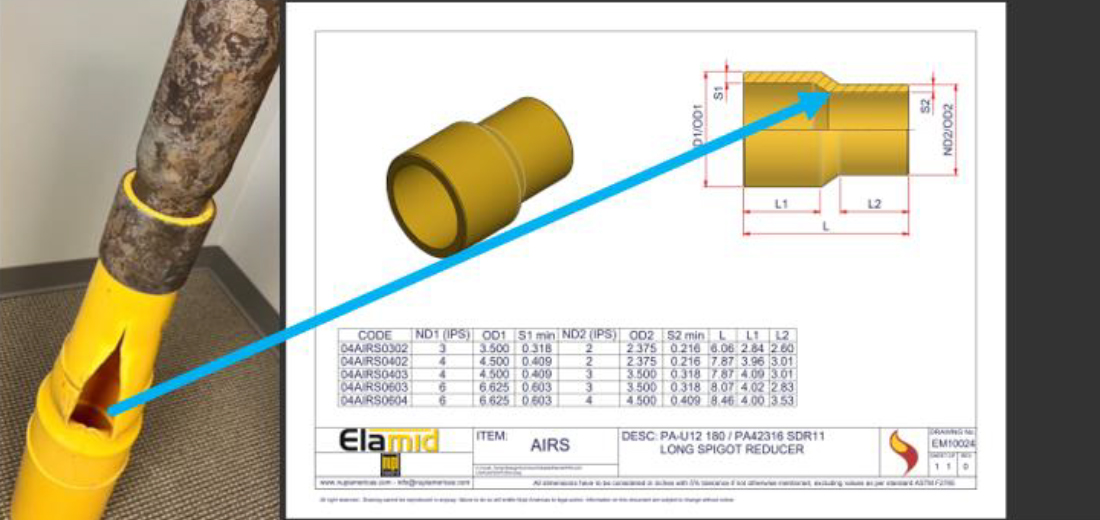
Figure 8. Review of the failure location and fitting design indicates the failure occurred at a transition in pipe thickness.
Conclusions
Upon completion of the full test plan, it was observed that all samples far exceeded the requirements of ASTM F2785-21. Successful bend-back results were accomplished in the field, tensile testing demonstrated an average weld strength (6,223 psi) consistent with the control sample strength (6,222 psi) and far beyond the required strength (3,900 psi), and sustained pressure testing resulted in a pipe strength more than three times maximum operating pressure (MAOP).
Consequently, it can be concluded that consistent, high-performing fusion joints can be expected when the guidelines provided in ASTM F2785-21 and ASTM F3372-20 are followed. Additionally, it can be concluded that PA12 has the capability to perform well beyond the standard MAOP for gas distribution.
Full report: https:/files.groebner.com/pdfs/2024-PA12CaseStudy-CoServ-Groebner-Evonik.pdf
